By Kareem ElFaramawi | July 26, 2021
Introduction
One device that recently came across our desks was a Huawei EchoLife optical network terminal. As part of our standard analysis, we dumped the flash chip on the device in order to analyze the firmware. If you haven’t already seen it, check out a previous Hardware Hacking 101 blog entry which goes over the basic process of identifying and dumping flash from a device.
In most cases, once we have a flash dump, an open-source tool like binwalk can handle the rest of the extraction. However, this was one of the rarer cases where considerably more work was needed before we could effectively extract the firmware to return the kernel and filesystems. In this blog post, we’ll go over the process of finding out what was wrong with the flash dump and how we repaired it.
Repairing a NAND Dump
Normal Attempt at Unpacking
The first thing we typically do with a NAND dump is run it through a carving
tool like binwalk to get an overall idea of its contents. This image was
fairly small, and only came back with a few results.
$ ls -lh Micron_MT29F1G08ABAEA_00-07FFFFFF.bin
-rwxr--r-- 1 user user 128M Apr  1 14:28 Micron_MT29F1G08ABAEA_00-07FFFFFF.bin

$ binwalk -eM Micron_MT29F1G08ABAEA_00-07FFFFFF.bin

DECIMAL       HEXADECIMAL     DESCRIPTION
--------------------------------------------------------------------------------
88664         0x15A58         CRC32 polynomial table, little endian
90516         0x16194         CRC32 polynomial table, little endian
91682         0x16622         CRC32 polynomial table, little endian
1048576       0x100000        UBI erase count header, version: 1, EC: 0x0, VID header offset: 0x800, data offset: 0x1000

$ tree -a _Micron_MT29F1G08ABAEA_00-07FFFFFF.bin.extracted
_Micron_MT29F1G08ABAEA_00-07FFFFFF.bin.extracted
├── 100000.ubi
└── ubifs-root
    └── 154857296
        └── flash_configA

3 directories, 1 file
Unfortunately, nothing got extracted automatically with binwalk, so we’ll have
to take a closer look at the results ourselves. From these results, we’re mainly
interested in the UBI header at 0x100000, since this will likely contain
several images of the different parts of the firmware. We can use ubireader to
pull out all images starting from that offset:
$ ubireader_extract_images -s 1048576 Micron_MT29F1G08ABAEA_00-07FFFFFF.bin

$ ls -alh ubifs-root/Micron_MT29F1G08ABAEA_00-07FFFFFF.bin
total 1.4M
drwxrwxr-x 2 user user 4.0K Jun 30 09:01 .
drwxrwxr-x 3 user user 4.0K Jun 30 09:01 ..
-rw-rw-r-- 1 user user 124K Jun 30 09:01 img-154857296_vol-flash_configA.ubifs
-rw-rw-r-- 1 user user 124K Jun 30 09:01 img-154857296_vol-flash_configB.ubifs
-rw-rw-r-- 1 user user 124K Jun 30 09:01 img-154857296_vol-slave_paramA.ubifs
-rw-rw-r-- 1 user user 124K Jun 30 09:01 img-154857296_vol-slave_paramB.ubifs
-rw-rw-r-- 1 user user 124K Jun 30 09:01 img-154857296_vol-system_param.ubifs
-rw-rw-r-- 1 user user 372K Jun 30 09:01 img-154857296_vol-ubootA.ubifs
-rw-rw-r-- 1 user user 372K Jun 30 09:01 img-154857296_vol-ubootB.ubifs
Right away, there are a few issues with the results here. We started out with a
128MB flash dump, yet only 1.4MB of data was extracted. From the naming scheme
of these images, we can see that two banks (A/B) are being used, so we should
expect to find 2 filesystems in the results. None of names or binwalk results
suggest that any of these contain filesystems, and the largest image is only
372K, so there’s definitely something missing here. Before looking more closely
at the image, we need to make sure we have all the data contained on the NAND
chip.
Extracting All Data (Main + Spare) From the NAND Chip
NAND flash chips are organized into blocks and pages of data. The entire chip is divided up into blocks, each of which contains a set number of pages. A page is simply a fixed-length chunk of data that is divided into two sections: the main area and the spare area.
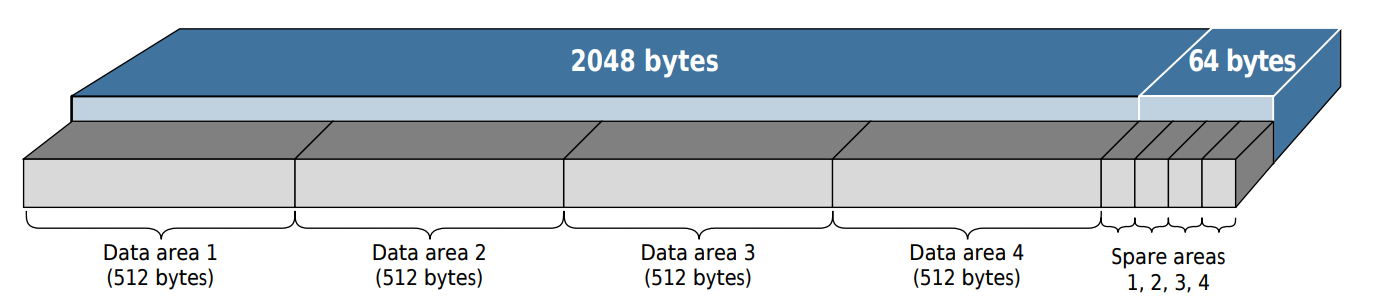
Example layout of a NAND page Source: Micron
The main area is where all the data we would normally be interested in is
stored, and takes up the majority of the page. A common length of this area is
2048 (0x800) bytes. The spare area is not functionally any different from the
main area, but is much smaller and typically used to store only bad block
markers, error correction codes (ECC), and any other metadata. A common size for
this is 64 (0x40) bytes.
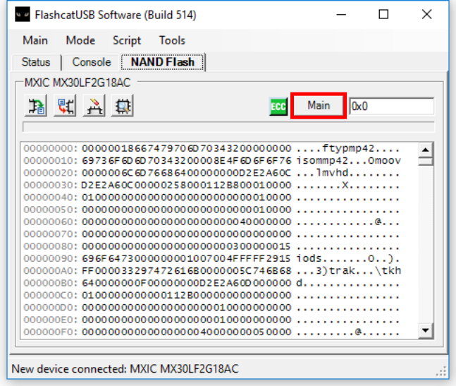
Normally when you dump a NAND chip, you will only get all the main areas
concatenated together, with the spare areas being ignored. Most tools will have
an option to read the spare area separately, or read each page in full as shown
above. For example, in Flashcat, NAND chips will show a button that says Main
by default. You can click this button until it says All to be able to dump the
full pages instead of just the main areas.
Now after dumping the chip with this setting, we get a slightly larger image that contains all of the spare area data in addition to what we had before.
$ ls -lh ALL_Micron_MT29F1G08ABAEA_00-083FFFFF.bin
-rw-r--r-- 1 user user 132M Apr  1 14:24 ALL_Micron_MT29F1G08ABAEA_00-083FFFFF.bin
Templating and Investigating the Flash Dump
To make looking through the NAND dump much easier we’ll be using 010 Editor, which is a hex editor with support for binary templates. This means we can define C-like structs and use them to parse the flash dump, allowing us to gain much better understanding of the structure and facilitate looking for problems.
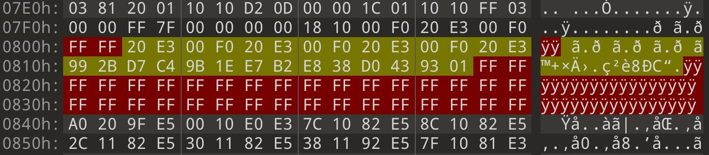
The first thing we need to do is identify the sizes of the main and spare areas so that we can parse them. To do this, we can compare the two flash dumps we have now, and only one of them will have the additional spare data in every page.
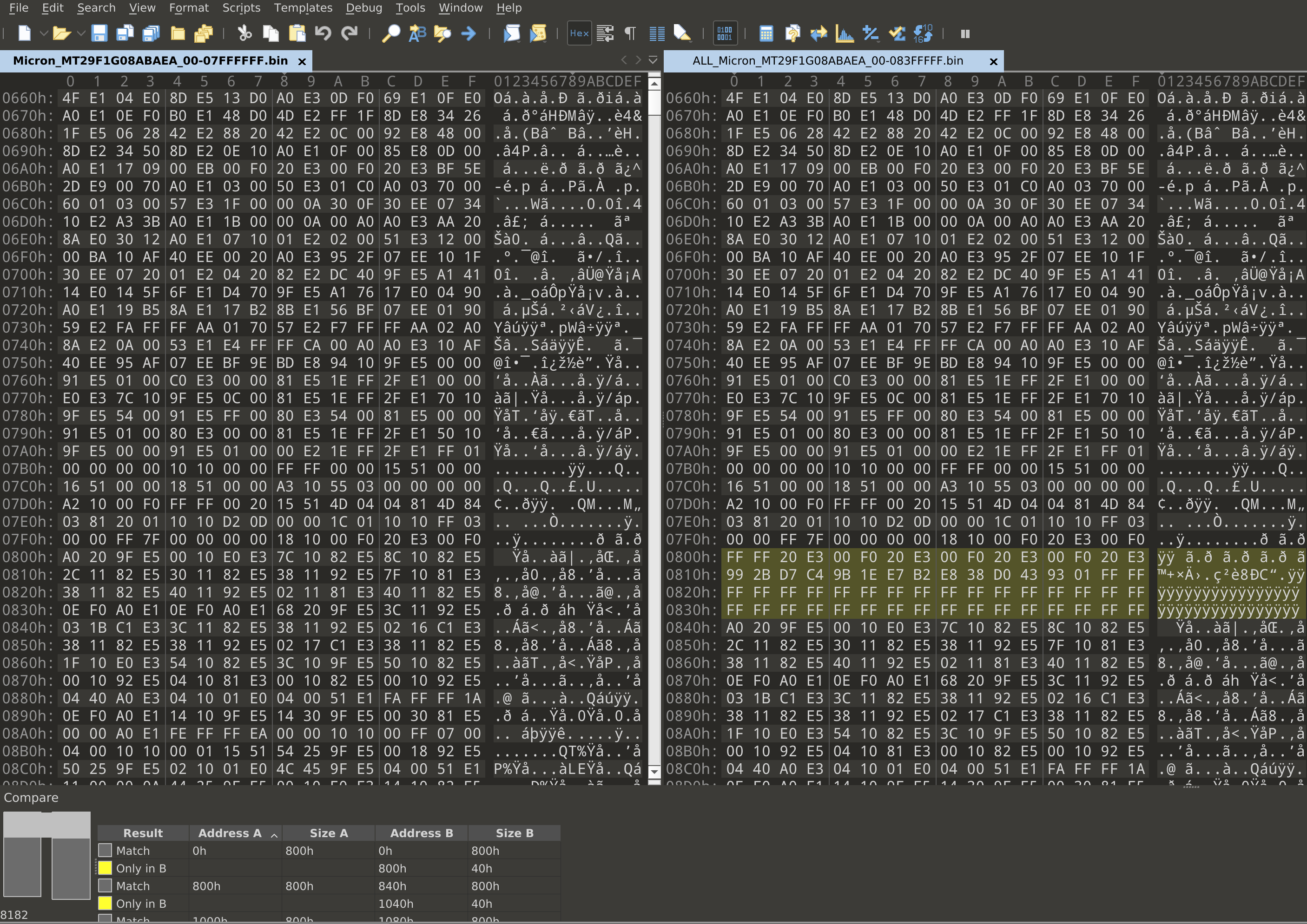
Here, we can see that the first 0x800 bytes match, and there are an additional
0x40 bytes inserted on the right side. So, we can conclude that this chip uses
the common sizes of 0x800 for main areas and 0x40 for spare areas. Now, lets
start writing a template that just highlights the spare areas throughout the
flash dump.
typedef struct {
    byte data[0x800];
} main_t;

typedef struct {
    byte data[0x40] <bgcolor=0x0000ff>;
} spare_t;

while (!FEof()) {
    main_t main;
    spare_t spare;
}
This template defines a main struct as 0x800 bytes, and a spare struct as
0x40 bytes of data that are highlighted in red. Then, it repeatedly creates
one of each until the end of the file. If we run this template on our flash
dump, we get something like this:
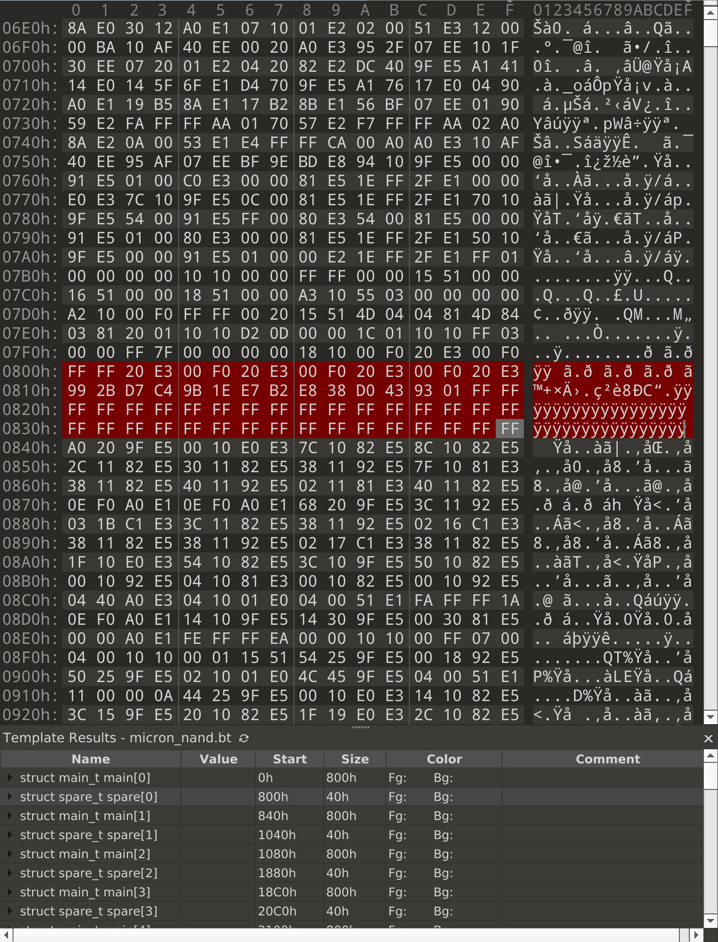
Our suspicion is that some of the data that belongs in the main area somehow ended up in the spare area instead. So first, let’s try to narrow down which bytes in the spare area might contain the missing data. After scrolling quickly through a lot of the highlighted areas, a vague pattern starts to show up:
- The first 2 bytes are always
FF - The next 28 bytes contain some kind of data
- The last 34 bytes are always
FF
From seeing this, we can hypothesize that our data lies somewhere in the 28 middle bytes. Let’s update the template highlighting to reflect this, and investigate further to see if we were right or wrong.
typedef struct {
    byte data[0x800];
} main_t;

typedef struct {
    byte bad1[2] <bgcolor=0x0000ff>;
    byte spare[28] <bgcolor=0x00ffff>;
    byte bad2[34] <bgcolor=0x0000ff>;
} spare_t;

while (!FEof()) {
    main_t main;
    spare_t spare;
}
Now that we have a good base template to start with, we can start looking
through the flash dump for anything that might be in the wrong place. Recall
that binwalk found a UBI header in this flash dump. UBI is a page-aligned
format, so anything that doesn’t fill up a page gets padded with some filler
bytes. Knowing this, we can look for any spots where the filler bytes aren’t the
same as the rest.
The first interesting page to look at is at 0x14A000:
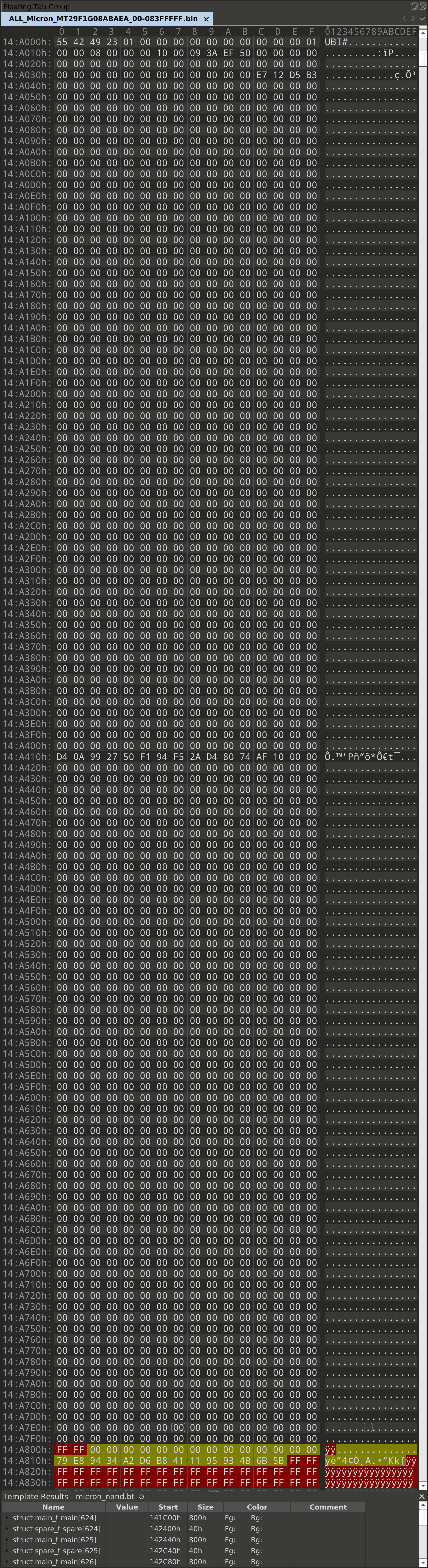
The UBI erase count header makes up only the first 0x40 bytes of this page.
Everything past this should be padding. As we can see from most of the image,
null bytes are used for padding in this page. So, we expect that everything
between 0x14A040 and 0x14A800 should be null bytes. But, looking at this
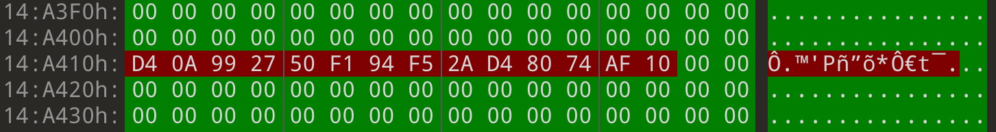
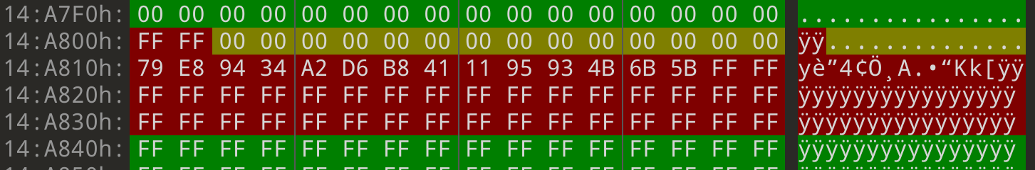
page, there’s a very obvious spot where this isn’t the case: at 0x14A410.
Here, we have 14 bytes in the middle of the page that aren’t null bytes. Where
did the null bytes that are supposed to be here go? Let’s look at what we
highlighted in the spare area. The yellow region has the 28 bytes
where we suspected the missing data had gone, and sure enough, the first 14
bytes in this region are all null bytes.
Before we try figuring out how to get this data back where it needs to be, let’s update the template to highlight what we’ve discovered. Having these structures written will make writing the repair script later on easier.
typedef struct {
    byte good1[0x410] <bgcolor=0x00ff00>;
    byte bad1[0xE] <bgcolor=0x0000ff>;
    byte good2[0x3E2]<bgcolor=0x00ff00>;
} main_t;

typedef struct {
    byte bad2[0x2] <bgcolor=0x0000ff>;
    byte good3[0xE] <bgcolor=0x00ffff>;
    byte bad3[0x30] <bgcolor=0x0000ff>;
} spare_t;

while (!FEof()) {
    main_t main;
    spare_t spare;
}
Now that we see all the parts we need, it’s time to put them together into a valid flash dump. One way to do this is using the library pfp, which allows you to use 010 Editor templates in python. However, due to the size of the flash dump this method ended up being too slow. Fortunately, our template is very simple, so we can mirror this easily in our own script.
#!/usr/bin/env python3
import sys

if len(sys.argv) != 2:
    print(f'usage: {sys.argv[0]} <nand dump (dumped with ALL in flashcat)>')
    exit(1)
fname = sys.argv[1]
fixed = f'{fname}.fixed'

with open(fname, 'rb') as fin:
    with open(fixed, 'wb') as fout:
        page = 0
        while True:
            print(f'Dumping page #{page}')
            page += 1

            # START OF PAGE
            good1 = fin.read(0x410)
            ecc2 = fin.read(0xE)
            good2 = fin.read(0x3E2)

            # START OF SPARE
            ecc1 = fin.read(0x2)
            good3 = fin.read(0xE)
            ecc3 = fin.read(0x30)

            if len(good1) == 0:
                break

            fout.write(good1 + good2 + good3)

print(f'DONE - saved to {fixed}')
This also makes it easy to try different methods of concatenating the good data together, but it turns out that keeping everything in the order it appears in the NAND dump results in a valid image. So in other words, we delete the 14 bad bytes in the middle of each page, and append the 14 bytes we found in the spare area to the end of the main area.
After running this script on our image, we get a new 128MB “fixed” image that should have what we need in it.
$ ls -lh ALL_Micron_MT29F1G08ABAEA_00-083FFFFF.bin.fixed
-rw-rw-r-- 1 user user 128M Jun 30 14:16 ALL_Micron_MT29F1G08ABAEA_00-083FFFFF.bin.fixed

$ ubireader_extract_images -s 1048576 ALL_Micron_MT29F1G08ABAEA_00-083FFFFF.bin.fixed

$ ls -lh ubifs-root/ALL_Micron_MT29F1G08ABAEA_00-083FFFFF.bin.fixed
total 58M
-rw-rw-r-- 1 user user 124K Jun 30 14:19 img-154857296_vol-flash_configA.ubifs
-rw-rw-r-- 1 user user 124K Jun 30 14:19 img-154857296_vol-flash_configB.ubifs
-rw-rw-r-- 1 user user 1.9M Jun 30 14:19 img-154857296_vol-kernelA.ubifs
-rw-rw-r-- 1 user user 1.9M Jun 30 14:19 img-154857296_vol-kernelB.ubifs
-rw-rw-r-- 1 user user  26M Jun 30 14:19 img-154857296_vol-rootfsA.ubifs
-rw-rw-r-- 1 user user  26M Jun 30 14:19 img-154857296_vol-rootfsB.ubifs
-rw-rw-r-- 1 user user 124K Jun 30 14:19 img-154857296_vol-slave_paramA.ubifs
-rw-rw-r-- 1 user user 124K Jun 30 14:19 img-154857296_vol-slave_paramB.ubifs
-rw-rw-r-- 1 user user 124K Jun 30 14:19 img-154857296_vol-system_param.ubifs
-rw-rw-r-- 1 user user 372K Jun 30 14:19 img-154857296_vol-ubootA.ubifs
-rw-rw-r-- 1 user user 372K Jun 30 14:19 img-154857296_vol-ubootB.ubifs
-rw-rw-r-- 1 user user 124K Jun 30 14:19 img-154857296_vol-wifi_paramA.ubifs
-rw-rw-r-- 1 user user 124K Jun 30 14:19 img-154857296_vol-wifi_paramB.ubifs
Now things are looking a lot better, we have new kernel, rootfs, and
wifi_param images that weren’t able to be extracted before. To start, let’s
try unpacking one of the rootfs images. This happens to be in a
router-specific format that’s simply a wrapper around a uImage header and data.
We made another template for pulling out the block of data we care about from
these files.
These rootfs files contained squashfs images inside them, so let’s try extracting them:
$ ./dump_uimage.py img-154857296_vol-rootfsA.ubifs rootfsA
$ file rootfsA
rootfsA: Squashfs filesystem, little endian, version 1024.0, compressed, 6763453368024170496 bytes, 772800512 inodes, blocksize: 512 bytes, created: Sat Feb  8 03:43:21 2042


$ unsquashfs rootfsA
Parallel unsquashfs: Using 12 processors
3573 inodes (3961 blocks) to write


lzma uncompress failed with error code 9

lzma uncompress failed with error code 9

write_xattr: could not write xattr security.capability for file squashfs-root/bin/Bbspcmd because you're not superuser!

write_xattr: to avoid this error message, either specify -user-xattrs, -no-xattrs, or run as superuser!

Further error messages of this type are suppressed!

lzma uncompress failed with error code 9

lzma uncompress failed with error code 9

lzma uncompress failed with error code 9

FATAL ERROR:writer: failed to read/uncompress file squashfs-root/bin/amp
As it turns out, all that ECC data was there for a reason - there are bit errors causing the LZMA decompression to fail, so we aren’t quite done with this yet.
Fixing Bit Errors Without ECC
Looking at the kernels and filesystems in both banks, we can see that they are the same on both sides with the exception of some single-bit errors.
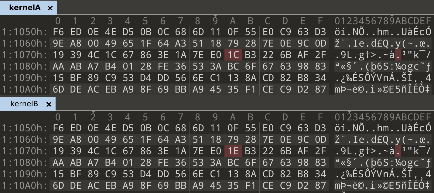
In [1]: bin(0x1C ^ 0x1E)
Out[1]: '0b10'
In normal cases, error correction could be handled either by the flash chip internally, or by a tool like Flashcat which would use the ECC data in the spare area. In our case, we don’t know which ECC algorithm is being used, and which parts of the spare area contain the correct ECC data. We could start guessing algorithms and parameters until something works, but there’s another way we can utilize what we have here to correct errors.
Kernel Extraction
The kernels and squashfs filesystems are both compressed using LZMA, which is a stream compression algorithm. So, if the decompression fails at one point due to a bit error, and then we fix it, it should be able to decompress more data on the next attempt. We know that at every byte where there’s a difference between the two banks, one of the two sides contains the correct byte. We can take advantage of this by trying both bytes and attempting decompression, then taking the one that resulted in a larger extraction as the correct byte. It’ll be easier to start trying this on the kernels, since those are each a single long LZMA stream.
The rough algorithm for fixing the LZMA stream is the following:
keep a "correct" stream, starting out as a copy of either bank
find all indices where the two banks don't match
for each mismatch:
    try placing both bytes in the correct stream and decompressing
    keep the byte that resulted in a longer decompression
As we go through the two banks, we end up creating a new image that picked out all of the correct bytes from both original banks. Using this simple method, we were able to generate a kernel that decompresses successfully.
$ ./fix_lzma_bits.py kernelA kernelB
Finding differences...
There are 28 differences
ORIG  LEN: 365564
OTHER LEN: 115041
0x1107a original: 0x1c - best char is 0x1c - 365564
ORIG  LEN: 365564
OTHER LEN: 335740
0x2751e original: 0x60 - best char is 0x60 - 365564
ORIG  LEN: 365564
OTHER LEN: 474545
0x2a672 original: 0xcf - best char is 0xc7 - 474545
ORIG  LEN: 474545
OTHER LEN: 698565
0x35527 original: 0x9e - best char is 0x1e - 698565
...
...
...
ORIG  LEN: 4830840
OTHER LEN: 4123167
0x186c5b original: 0x27 - best char is 0x27 - 4830840

Saving result to kernelA.out
$ binwalk -eM kernelA.out
DECIMAL       HEXADECIMAL     DESCRIPTION
--------------------------------------------------------------------------------
0             0x0             Linux kernel ARM boot executable zImage (little-endian)
2380          0x94C           device tree image (dtb)
18340         0x47A4          LZMA compressed data, properties: 0x5D, dictionary size: 67108864 bytes, uncompressed size: -1 bytes
1792888       0x1B5B78        device tree image (dtb)
1795864       0x1B6718        device tree image (dtb)
1798872       0x1B72D8        device tree image (dtb)
...

$ tree _kernelA.out.extracted
_kernelA.out.extracted
├── 47A4
├── 47A4.7z
└── _47A4.extracted
    ├── 312BD8
    ├── 3D60E8.xz
    ├── 4535D8.cpio
    ├── console
    ├── cpio-root
    │   ├── dev
    │   └── root
    ├── dev
    └── root
SquashFS Extraction
Unfortunately, things aren’t as easy when trying this on the squashfs. Instead of one long stream, this format splits data up into many small blocks and compresses them separately. To deal with this, we’re going to need a stronger measure than simply checking which extraction is longer.
LZMA Header
The overall structure of an LZMA stream is fairly simple: there is a short 13 byte header, followed by the full compressed stream.

| Name | Length (Bytes) | Description |
|---|---|---|
| Properties byte | 1 | Compression options encoded as a single byte |
| Dictionary size | 4 (little endian) | Size of the dictionary used for compression |
| Uncompressed size | 8 (little endian) | Size of the resulting decompressed data |
Of these, we’re interested in the uncompressed size field. We can utilize this to check if our decompression attempt was successful - if using one of the bytes results in the right size but the other doesn’t, we choose the one that does. There are still a few more issues we must account for before we’re able to fix the filesystem.
- What if both bytes result in the same size?
- What if the error is in the size field itself?
- What if neither byte results in the correct uncompressed size?
Case 3 is easy, we just do what we did before and take the one that resulted in a larger size. For cases 1 & 2, there is no way to determine which byte is correct at that point. Instead, we’ll have to branch and consider both bytes as options in the final result. This now looks like a depth-first search, where we branch any time one of those conditions are met. By taking all of these cases into account, we drastically cut down the number of branches we need to take and take fewer incorrect paths. Otherwise, if this was a pure brute force of attempting all possible byte combinations, the search space and runtime would have grown exponentially large.
$ ./fix_lzma_bits.py rootfsA rootfsB --squashfs
Finding differences...
There are 378 differences
ORIG  LEN: 131072
OTHER LEN: 113077
0x906d original: 0xc2 - best char is 0xc2 - 131072
ORIG  LEN: 92564
OTHER LEN: 121152
0x11fdc original: 0xf6 - best char is 0xb6 - 121152
ORIG  LEN: 84896
OTHER LEN: 131072
0x2efdd original: 0xbd - best char is 0xbc - 131072
...
...
...
0x19d1a68 original: 0x1 - best char is 0x1 - 130993

Saving result to rootfsA.out


 ATTEMPTING EXTRACTION...


Parallel unsquashfs: Using 12 processors
3573 inodes (3961 blocks) to write

[===================================================] 3961/3961 100%

created 3331 files
created 569 directories
created 237 symlinks
created 5 devices
created 0 fifos
SUCCESS
Using this new algorithm and a maximum depth of 1 branch, the filesystem was
fully repaired after running for about 6 minutes. A pure brute force would have
taken 2^378 attempts at extraction, which would never have terminated.
After all this, we finally have a Linux filesystem that we can look through for further analysis:
$ ls -l squashfs-root
total 84
drwxr-xr-x  2 root root 12288 Aug  4  2017 bin
drwxr-xr-x  2 root root  4096 Aug  4  2017 boot
drwxr-xr-x  4 root root  4096 Aug  4  2017 dev
drwxr-xr-x 18 root root  4096 Aug  4  2017 etc
drwxr-xr-x  8 root root  4096 Aug  4  2017 html
drwxr-xr-x  7 root root 12288 Aug  4  2017 lib
drwxr-xr-x  3 root root  4096 Aug  4  2017 libexec
drwxr-xr-x  4 root root  4096 Aug  4  2017 mnt
drwxr-xr-x  2 root root  4096 Aug  4  2017 proc
drwxr-xr-x  2 root root  4096 Aug  4  2017 root
drwxr-xr-x  2 root root  4096 Aug  4  2017 sbin
drwxr-xr-x  3 root root  4096 Aug  4  2017 share
drwxr-xr-x  2 root root  4096 Aug  4  2017 sys
drwxr-xr-x  2 root root  4096 Aug  4  2017 tmp
drwxr-xr-x  3 root root  4096 Aug  4  2017 uer
drwxr-xr-x 10 root root  4096 Aug  4  2017 usr
drwxr-xr-x  2 root root  4096 Aug  4  2017 var
lrwxrwxrwx  1 root root    12 Aug  4  2017 linuxrc -> /bin/busybox
Conclusion
In this blog post, we covered how to write a binary template to assist in the process of repairing a NAND dump, and a technique for correcting single-bit errors when ECC isn’t available. We hope you can take away something new to apply to your own flash analysis. Feel free to contact us with any questions, or to figure out how we can help you with embedded device analysis and security.