By Sue Mohieldin | July 8, 2021
Introduction
Welcome back to our introduction to hardware hacking 101 and the final installment of the JTAG blog post series! In this post we cover how to communicate with a target device via JTAG once the pinout has been identified. We walk through Open On-Chip Debugger (OpenOCD) and GDB (GNU project debugger), demonstrate how to read and write from memory, and more broadly discuss the impacts of an exposed JTAG interface on production devices. If you haven’t already, make sure to check out our previous JTAG posts: in part 1 we provide background on JTAG and in part 2 we share a teardown of a TP-Link AC1750 to demonstrate how to identify and verify a pinout for JTAG.
Background on OpenOCD
We continue our work on the TP-Link Archer C7 | AC1750 dual band wireless router. Previously, we verified the MIPS EJTAG 14 pinout for the device and identified the 5 primary signals: TCK, TMS, TDO, TDI and TRST (test reset input). We use this pinout to connect the Segger J-Link, which is a full-featured JTAG debugger that is compatible with OpenOCD.
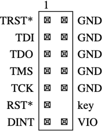
TP-Link’s MIPS 14-pin EJTAG Interface Source: MIPS Technologies Inc.
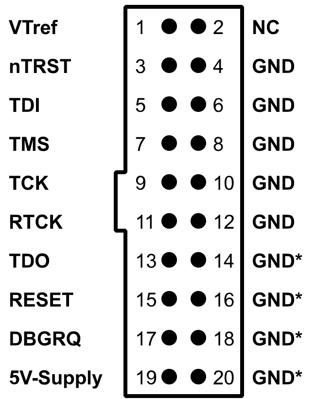
J-Link Pinout. Source: SEGGER
As a reminder, the reason that we are using OpenOCD and GDB (GNU Project debugger) is because the J-Link does not have a Qualcomm-Atheros configuration built in. OpenOCD is an open-source project that allows in-system programming, boundary scan testing and debugging for various MIPS and ARM systems. Running GDB simultaneously with OpenOCD allows us to further investigate what is going on while OpenOCD executes and allows us to perform actions such as stepping through a program if required.
Setting up OpenOCD and GDB
OpenOCD can be installed on Linux by running sudo apt install openocd
or cloning the repository using git clone git://openocd.git.sourceforge.net/gitroot/openocd/openocd . Similarly, GDB can be installed on Linux by running the following command: sudo apt install gdb-multiarch.
Now that we have both programs installed, we need a configuration file for the target device, which will enable us to communicate with the MIPS-based QCA9558-AT4A processor. OpenOCD provides a guide for how to write these configuration files from scratch: http://openocd.org/doc/html/Config-File-Guidelines.html.
Luckily for us, an ath79.cfg file already exists courtsey of OpenWRT: https://openwrt.org/docs/guide-user/hardware/debrick.ath79.using.jtag#ath79cfg. The configuration file should be copied to openocd/tcl/target
Working with OpenOCD and GDB
Now that OpenOCD and GDB are set up, we can start to interact with the JTAG interface on the TP-Link Archer C7. We will connect TCK, TMS, TDI, TDO, TRST, VIO (Vref) and GND from the TP-Link to that of the J-Link using female-female 2.54mm jumper wires. It is particularly important to connect TP-Link’s VIO pin to Vtref as the device operates on 2.61V. Furthermore, connecting TRST from the TP-Link to J-LINK’s nTRST will allow us to reset the JTAG tap controller when needed.
With the J-Link connected, we power on the router and let it boot. Next, we run OpenOCD using the following command, where we specify the J-Link interface, the ath79 target device and adapter speed:
$ sudo ./openocd -s ../tcl -f interface/jlink.cfg -f target/ath79.cfg -c "adapter speed 15000"
When connected successfully, we see that port 3333 can be used for a GDB connection, 4444 for a telnet connection, and 6666 for tcl. Furthermore, the adapter speed that we had set should be returned as the clock speed, the target voltage should be ~2.61V and an ath79 device should be recognized indicating that we can communicate with the chip.
Open On-Chip Debugger 0.11.0+dev-00035-g8d6f7c922-dirty (2021-03-16-19:11)
Licensed under GNU GPL v2
For bug reports, read
  http://openocd.org/doc/doxygen/bugs.html
Info : auto-selecting first available session transport "jtag". To override use 'transport select <transport>'.
adapter speed: 15000 kHz

Info : Listening on port 6666 for tcl connections
Info : Listening on port 4444 for telnet connections
Info : J-Link V9 compiled Feb  2 2021 16:34:10
Info : Hardware version: 9.30
Info : VTarget = 2.605 V
Info : clock speed 15000 kHz
Info : JTAG tap: ath79.cpu tap/device found: 0x00000001 (mfg: 0x000 (<invalid>), part: 0x0000, ver: 0x0)
Info : starting gdb server for ath79.cpu on 3333
Info : Listening on port 3333 for gdb connections
In a different terminal, we can open a telnet session to verify that we are connected to the device. For testing purposes, we will reset the device (note this does not reset the entire device since we do not have the RST pin connected rather just nRST) and check whether it still detects the processor and its ID.
$ telnet localhost 4444
Trying 127.0.0.1...
Connected to localhost.
Escape character is '^]'.
Open On-Chip Debugger
>reset
JTAG tap: ath79.cpu tap/device found: 0x00000001 (mfg: 0x000 (<invalid>), part: 0x0000, ver: 0x0)
As seen, the device 0x00000001 was returned, confirming that we are connected.
In another terminal session we can run GDB and keep it running in the background to debug any issues that might arise when using OpenOCD.
$ gdb extended-remote :3333
From the telnet session, we can read memory, dump flash and more. For this tutorial, we probe the flash and try to dump its contents. To do this, we must bypass the watchdog by halting the processor via halt. We will then perform reset init to disable the flash from remapping, which is specific to the ath79 configuration file.
> halt; reset init
MIPS32 with MIPS16 support implemented
target halted in MIPS32 mode due to debug-request, pc: 0x800064e0
JTAG tap: ath79.cpu tap/device found: 0x00000001 (mfg: 0x000 (<invalid>), part: 0x0000, ver: 0x0)
target halted in MIPS32 mode due to debug-request, pc: 0x800064e0
Next, we probe the flash and determine whether it can be identified.
 >halt; flash probe 0
target halted in MIPS32 mode due to debug-request, pc: 0x800064e0
Found flash device 'win w25q128fv/jv' (ID 0x001840ef)
flash 'ath79' found at 0xbf000000
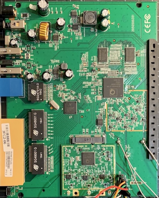
As shown, a ‘win w25q128fv’ located at 0xbf000000 was identified. Looking at the chips we previously identified, we see that there is a winbond 25Q128FVSG on the board, confirming that OpenOCD is correctly identifying the flash chip in use.
From here, we can get more information on the flash:
> halt; flash info 0
#0 : ath79 at 0xbf000000, size 0x01000000, buswidth 0, chipwidth 0
  #  0: 0x00000000 (0x10000 64kB) protected
  #  1: 0x00010000 (0x10000 64kB) protected
  #  2: 0x00020000 (0x10000 64kB) protected
  #  3: 0x00030000 (0x10000 64kB) protected
  .
  .
  .
  #250: 0x00fa0000 (0x10000 64kB) protected
  #251: 0x00fb0000 (0x10000 64kB) protected
  #252: 0x00fc0000 (0x10000 64kB) protected
  #253: 0x00fd0000 (0x10000 64kB) protected
  #254: 0x00fe0000 (0x10000 64kB) protected
  #255: 0x00ff0000 (0x10000 64kB) protected

ATH79 flash information:
  Device 'win w25q128fv/jv' (ID 0x001840ef)
We can then dump the flash:
> halt; dump_image flashdump.bin 0x00000000 0xF90600
Once dumped, we can examine and extract the binary file. For example, we can analyze the file using binwalk and grep for strings as shown below.
DECIMAL       HEXADECIMAL     DESCRIPTION
--------------------------------------------------------------------------------
70400         0x11300         Certificate in DER format (x509 v3), header length: 4, sequence length: 64
92640         0x169E0         U-Boot version string, "U-Boot 1.1.4 (Dec 17 2013 - 16:37:27)"
92816         0x16A90         CRC32 polynomial table, big endian
131072        0x20000         TP-Link firmware header, firmware version: 0.0.3, image version: "", product ID: 0x0, product version: -956301310, kernel load address: 0x0, kernel entry point: 0x80002000, kernel offset: 16252928, kernel length: 512, rootfs offset: 853546, rootfs length: 1048576, bootloader offset: 15204352, bootloader length: 0
131584        0x20200         LZMA compressed data, properties: 0x5D, dictionary size: 33554432 bytes, uncompressed size: 2442764 bytes
1179648       0x120000        Squashfs filesystem, little endian, version 4.0, compression:lzma, size: 5643337 bytes, 683 inodes, blocksize: 131072 bytes, created: 2013-12-17 08:56:12
Example of some strings:
$ strings -n15 flashdump.bin
ath_sys_frequency
ath_ddr_initial_config
U-Boot 1.1.4 (Dec 17 2013 - 16:37:27)
ath_gmac_miiphy_write
ath_gmac_miiphy_read
ath_gmac_enet_initialize
Multi-File Image
gzip compressed
bzip2 compressed
lzma compressed
unknown compression
Automatic boot of image at addr 0x%08lX ...
tftpboot- boot image via network using TFTP protocol
[loadAddress] [bootfilename]
The hell do you want flinfo for??
bootargs=console=ttyS0,115200 root=31:02 rootfstype=jffs2 init=/sbin/init mtdparts=ath-nor0:256k(u-boot),64k(u-boot-env),6336k(rootfs),1408k(uImage),8256k(mib0),64k(ART)
bootcmd=bootm 0x9f020000
baudrate=115200
TP-LINK Technologies
$ strings -n15 flashdump.bin | grep boot
bootm   - boot application image from memory
    - boot application image stored in memory
passing arguments 'arg ...'; when booting a Linux kernel,
Automatic boot of image at addr 0x%08lX ...
tftpboot- boot image via network using TFTP protocol
[loadAddress] [bootfilename]
tftpboot 0x8022c090 uImage; bootm 0x8022c090
Autobooting in %d seconds
$ strings -n5 flashdump.bin | grep image
## Booting image at %08lx ...
bootm   - boot application image from memory
    - boot application image stored in memory
'arg' can be the address of an initrd image
Automatic boot of image at addr 0x%08lX ...
tftpboot- boot image via network using TFTP protocol
Other actions that we can do include erasing and rewriting parts of flash memory, reading and writing register values, displaying the flash content, resetting the device, and more.
Impacts and Conclusion
In this JTAG blog post series, we first provided background information on the JTAG interface and discussed its state machine and electrical characteristics. We then demonstrated how to locate JTAG on a target device, identify its pinout, and showed how to communicate with JTAG via OpenOCD and perform actions such as dumping flash memory.
While an exposed JTAG interface may be useful when debugging and programming a device, it can also be exploited by attackers if not disabled or otherwise protected on a production device. In the example that we shared, we were able to extract and read the unencrypted contents from the Winbond 25Q128FVSG SPI flash chip. We also had the ability to erase and write to memory. From a cybersecurity perspective, JTAG enables an adversary to gain low-level control over the chip it is debugging. For instance, an attacker could halt the processor, change the program counter, bypass watch dogs and have read/write access to firmware.
We hope you enjoyed this multi-part JTAG series, feel free to contact us with any questions about how we can help test the security of a system, design more secure devices, or help you in other ways related to connected device security.